Friday, June 9, 2017

NEC IR Decoder with PIC Microcontroller

This is a final project for a class in the Spring of 2017 (Embedded Systems class).  I really enjoyed that class, and for the final project we got a lot of freedom to choose a PIC microcontroller and come up with a project (approved by Professor) on our own.  The following is the report contents for my project.  There's one bug in particular I want to squash, and which I have some theories on what could be causing it but I've got too much to do (work, social life, other projects, etc.).  It will false detect, and return a command code of 0xFF, I believe the LED is emitting IR light and tricking my IR receiver, but I haven't verified yet.  Anyway, this project works and I may expand it to do something useful like controlling a media system or something like that, with my phone or any NEC IR remote control.


INTRODUCTION:
My project was to use a PIC18F27K40-I/SP 8-bit PIC microcontroller to receive an infrared (IR) signal from an IR remote (as well as one of my smartphones with an IR transmitter on it) using the NEC protocol, display that character or command sent to the receiver on an Liquid Crystal Display (LCD), and use pulse width modulation (PWM) to beep a speaker every time a command is received.
The IR receiver is a TSOP4838. The microcontroller is an advanced 8-bit device (18F PIC series). There is more memory and a few more ports on this microcontroller but it was not needed for this project. I wanted to be safe hardware-wise though. NEC Electronics was the company that came up with the protocol used, and that company is now called Renesas.
REQUIREMENTS:
The requirements for a single-person group was to use at 3 peripherals. The peripherals I used were digital I/O (IR encoding protocol for data), an LCD, and PWM. No more peripherals were added since I did not have the time to, but there is plenty of space for adding more. I was able to satisfy my project proposal and get the commands displayed on an LCD screen and beep every time a command was received.
HARDWARE DESIGN DETAILS:
Refer to the “Parts Used” section for what hardware was used. A schematic and layout of the hardware used is pictured below in Figure 1. An assortment of standard parts was used, a speaker, an IR receiver, a couple of resistors, an LED, a power supply, and LCD. A slightly non-standard part was a serial-to-LCD converter module. This allowed me to use only one pin for the LCD instead of 11, saving space to expand for other peripherals or features.
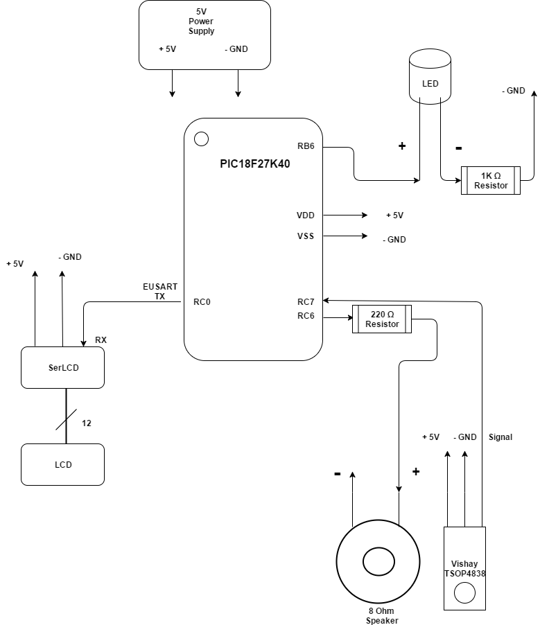
Figure 1: Project Schematic / Layout

SOFTWARE DESIGN DETAILS:
The software was intentionally simplistic, using a polling method for the IR receiver in a while loop and no interrupts. I do all the initializing of the peripherals at power up:
  • Making one pin a digital input for the IR receiver
  • Making one pin a digital output for an LED
  • Setting up a timer and an output pin for PWM
  • Setting up a EUSART port with a TX pin for the LCD.
Once everything is initialized, I have a while-loop that reads the IR pin. If the pin is high, I just wait until it goes low. I do this to make sure that I do not miss an incoming command, the timing is important. When the pin goes low I begin looking for a high pulse for 9 milliseconds. I do this with a counter variable and a delay function that is in one of the compiler libraries for the PIC. The function is “__delay_us()”, and it delays for the amount of microseconds put in the parentheses. After the 9 milliseconds high, I look for 4.5 milliseconds low. Then after waiting for that amount of time, I can start looking for the actual payloads in the message. First is an 8-bit address, then that address is inverted. After that the command is sent, then that command is inverted. I did not do any error checking but in a commercial product you would check each address and command to be sure they are total opposites of each other, before accepting the command. If the timing was for a logical 1 or 0, then that particular bit is set in an unsigned 32 bit variable. After getting the command, having a small delay for the beep of the speaker prevents “loop-back” or getting another command immediately after. It is a kind of “debounce”, like you would do for buttons.


Figure 2: Software Flowchart Diagram

IMPLEMENTATION DETAILS:
The NEC protocol is a very popular IR protocol. It originally had an 8-bit command length, but those commands were quickly used up by vendors. An expanded 16-bit version was created, allowing for around 65,535 commands to be used. My decoder currently is only 8-bit however. The protocol starts with a 9 millisecond pulse high, then a 4.5 millisecond pulse low, then it begins with an 8 bit address, the inversion of that address, then an 8 bit command, and the inverted command. 


Figure 3: NEC IR Protocol

EXPERIMENT RESULTS AND DISCUSSION:
I was having a little trouble getting the address for some reason, but for my remote I know it is 0xFF. Getting the command is the most important part and I know I was getting the correct command. An excellent IR library [7] for the Arduino platform was used to verify that my codes are correct. In the reference section below I will attach all the commands from the IR remote. I visually verified with the Arduino IR library that it was working with the IR transmitter on my phone, which has an application that can transmit just about all the IR protocols for TV remotes. The Vizio remote I use on my Android phone for a Vizio TV happened to be NEC protocol and works with the decoder.

REFERENCES:
[1] https://www.sparkfun.com/products/258
[2] https://www.sparkfun.com/products/255
[3] http://uk.farnell.com/vishay/tsop4838/ir-receiver-38khz/dp/4913190
[4] http://www.microchip.com/wwwproducts/en/PIC18F27K40
[5] http://www.sbprojects.com/knowledge/ir/nec.php
[6] http://techdocs.altium.com/display/FPGA/NEC+Infrared+Transmission+Protocol#
[7] https://github.com/z3t0/Arduino-IRremote

APPENDIX:
  1. The codes for one of the IR transmitters are listed below. They include the address (8 bits, not the inverted portion) and the command with the inverted command.
Gray remote control button commands, starting with top left (red power button) and going right, then next row, etc.
FFB24D
Decoded NEC: FFB24D (32 bits)
FF2AD5
Decoded NEC: FF2AD5 (32 bits)
FF6897
Decoded NEC: FF6897 (32 bits)
FF32CD
Decoded NEC: FF32CD (32 bits)
FFA05F
Decoded NEC: FFA05F (32 bits)
FF30CF
Decoded NEC: FF30CF (32 bits)
FF50AF
Decoded NEC: FF50AF (32 bits)
FF02FD
Decoded NEC: FF02FD (32 bits)
FF7887
Decoded NEC: FF7887 (32 bits)
FF48B7
Decoded NEC: FF48B7 (32 bits)
FF40BF
Decoded NEC: FF40BF (32 bits)
FF38C7
Decoded NEC: FF38C7 (32 bits)
FF906F
Decoded NEC: FF906F (32 bits)
FFB847
Decoded NEC: FFB847 (32 bits)
FFF807
Decoded NEC: FFF807 (32 bits)
FFB04F
Decoded NEC: FFB04F (32 bits)
FF9867
Decoded NEC: FF9867 (32 bits)
FFD827
Decoded NEC: FFD827 (32 bits)
FF8877
Decoded NEC: FF8877 (32 bits)
FFA857
Decoded NEC: FFA857 (32 bits)
FFE817
Decoded NEC: FFE817 (32 bits)
  1. Only the main.c file is included here as it is where the main application code is, for the rest of the code, refer to the zip file included with the project submission.
/*
* File: main.c
* Author: Int-Mosfet
*
* Created on April 8, 2017, 11:41 AM
*/

#include <stdio.h>
#include <stdlib.h>
#include "pin_manager.h"

#define SET_BIT(var, pos) (var |= (1 << pos))
#define CLEAR_BIT(var, pos) (var &= (~(1 << pos)))

void main(void)
{
// Initialize the device
SYSTEM_Initialize();
//turn on LED
IO_RB6_SetHigh();
//turn off PWM
//1 is off, 0 is on (PWM)
TRISCbits.TRISC6 = 1;
// Value loaded effects volume output
//PWM3_LoadDutyValue(0xF0);
//TRISCbits.TRISC6 = 0;
//__delay_ms(500);
//TRISCbits.TRISC6 = 1;
//RC6_SetLow();
uint8_t count = 0;
uint8_t i = 0;
//control char of 254 (0xFE)
//must be sent before a command)
uint8_t cntr = 254;
uint8_t clear_cmd = 1;
volatile uint32_t ir_code;
uint16_t address;
uint8_t command, inv_command;
//Clear screen
//EUSART1_Write(cntr);
//EUSART1_Write(clear_cmd);
//set cursor to beginning
//EUSART1_Write(cntr);
//EUSART1_Write(128);
__delay_ms(2000);
printf("ECE471 IR Decode");
printf("NEC Proto, Begin");
while (true)
{
//delay until RC7 goes low
while(IO_RC7_GetValue() == 1);
//9ms high
while((IO_RC7_GetValue() == 0) && (count < 200))
{
count++;
__delay_us(50);
}
//if(count > 200 || count < 160)
// printf("FALSE ACTIVATION");
//reset counter
count = 0;
//4.5ms low
while((IO_RC7_GetValue()) && (count < 100))
{
count++;
__delay_us(50);
}
//if(count > 100 || count < 80)
// printf("FALSE ACTIVATION");
// Read IR code, 32 bits
for(i = 0; i < 32; i++)
{
count = 0;
while((IO_RC7_GetValue() == 0) && (count < 14))
{
count++;
__delay_us(50);
}
count = 0;
while((IO_RC7_GetValue()) && (count < 40))
{
count++;
__delay_us(50);
}
if( count > 20)
SET_BIT(ir_code, (31 - i));
else // If space width < 1ms
CLEAR_BIT(ir_code, (31 - i));
}
address = ir_code << 16;
command = ir_code >> 4;
//clear screen
EUSART1_Write(cntr);
EUSART1_Write(clear_cmd);
printf(" NEC PROTOCOL");
//printf(" CMD: ");
//printf("%x", command);
//printf(" ");
EUSART1_Write(cntr);
EUSART1_Write(192);
printf("FULL CODE: ");
printf("%x", ir_code);
printf(" ");
TRISCbits.TRISC6 = 0;
__delay_ms(200);
TRISCbits.TRISC6 = 1;
}
}
  1. List of Figures:
  • Figure 1: Project Schematic / Layout
  • Figure 2: Software Flowchart Diagram
  • Figure 3: NEC IR Protocol
  1. Parts Used:
  • PIC18F27K40-I/SP 8-bit PIC microcontroller
  • 16 X 2 LCD screen (LCD-00255)
  • Serial Enabled LCD Backpack (LCD-00258)
  • Vishay TSOP4838 Infrared receiver, 38kHz
  • 8 Ω speaker
  • 220 Ω current-limiting resistor for speaker
  • 1 K Ω current-limiting resistor for LED
  • Breadboard
  • 3-30V Volt-meter (extra add-on)
  • Jumper wire
  • Alligator clips
  • 5V power supply

USB-To-Serial Data Diode and Secure File Transfer Method For Windows PC's

This was a fun project.  Computer security is a big hobby of mine.  There's a thing called a "data diode" which is meant to enforce one-way communication from an isolated and secured node to an unsecured node (you can have multiple "secured nodes" if you want).  I had been wanting to build one of these for a long time but never knew how!  Whichever device you use to transmit, needs to be as secured as you can possibly make it, no malware, no side-stepping the data diode via wifi, bluetooth, audio, optical, or other RF channels.  From the insecured node you connect to a network like the internet and transfer the file to another recipient, and they push the file one way to a receiving computer.  The purpose of doing this is keeping malware off machines which you transfer files to and from.  Also, mainly for doing encryption and zipping of a file not on a networked device, which could be keylogging the plaintext material.  If there's a keylogger on your offline PC, it would have to encode that information into the encrypted and zipped file, which is feasible but would probably be noticeable. It becomes much harder when you just take away the network aspect (internet).  Requires some fancy end-run attacks.

The design I was testing was this one located here, I'll link some of the pictures on this blog post too:  imgur.com/a/5Cv19

Very simple, nice design.  I won't repeat much of what's there.  The optocoupler used was an Avago HCPL 7723, this is the most important part enforcing isolation of TX and RX pins, to deal with potential of pin-remapping on USB-Serial converters (highly unlikely but probably possible).  If you can do this with discrete parts and not an IC, it would be easier to verify and catch potential hardware backdoors in the optocoupler.  There is a design here for such a thing: (link Uni of Iowa paper on data diodes).  The other part is an FTDI232 USB-serial converter board.  You can get those really cheap, like $6 for 2.  The optocoupler seemed unnecessarily expensive...$22.  I just used that one since that was original design called for, any optocoupler would work I believe.  I would like a cheaper optocoupler.

My contribution here though was I wanted file transfer, that's useful.  The guy who made this design (who I'm leaving nameless for now) only did some basic experiments (for time reasons I think) and sent some characters over the data diode and checked with an oscilloscope to verify it worked.  I was pretty confident some terminal programs would work to send full files over it.  Thankfully one terminal program did work, Realterm.  The problem for me is I want to know exactly how the file is being sent and it's not very clear in the Realterm docs and I couldn't get access to the code just yet.

So first off you need to install any FTDI virtual comm. port drivers if you don't already have some installed (don't need this on Linux usually as these drivers usually get included in the kernel, but I haven't tried Realterm via Wine on Linux).  Then you need to install Realterm on each device.  Next you'll need to build the data diode.  For now, I just soldered wires directly to the optocoupler pins, as well as soldering the 47nF capacitor again directly to the pins (the capacitor acts as a low pass filer, it's a necessary component according to the datasheet).  You connect +5V and GND pins from each USB-serial converter, and *ONLY* the TX pin on the TX side, and the RX pin on the RX side.  This is very important, in essence you have 2 things that are enforcing the isolation of transmitting one way.  First, by not even connecting an RX pin back to TX, then the enforcing of the unidirectional path for data flow with the optocoupler which has an LED on one side, and a photodiode on the other.  Tranducers are bidirectional however, a simple experiment to try is to take an LED, attach a digital multimeter to it, and shine a flashlight on the LED, you will see some voltage.  Depending on the strength of the flashlight it may get up to 1.3 or even 2V, which may be enough to do something.  It may still be possible (though highly highly unlikely) to inject enough power via RF or optical channels to turn the photodiode into a transmitter and the LED will receive that, but I think it would be a ridiculously high level.  I'm not sure, that's an experiment to try sometime.

Be careful that you do not connect anything to pins 3 or 7 on the optocoupler, or it will not work.  I can tell you that for sure.

I used the male-female wire connectors that you typically get with an Arduino kit, however you wire it up is up to you, but I do want to make a simple PCB for this.  Once you have your data diode made, connect each side to your TX computer and RX computer, you'll need some mini-to-normal USB cables for this as well of course.  Create some make up file, for this example I'll transmit this text file I'm making and take pictures for the blog post. 

Once file is created, open up Realterm (installing Realterm should be very easy so I'm skipping over that).  Click on the "Port tab", let's keep the baud rate at the default of 57600 (but I've tried it 115200 and it still worked), now you need to see what port your USB Virtual Comm. Port is at, it can be different numbers.  You need to find which one it is, for me it's #3.  Leave all the other settings alone, they're fine.  Once you have your port setup, you click on the "Change" button with the green check mark.  Now setup your RX side, same thing, set the baud rate at 57600, find what USB Virtual Comm. Port you use, for me it's #11, then go to the "Echo Port" tab, and use the same settings for baud rate and the Port, click on the "Echo On" and the "Monitor" check box, then hit the "Change" button with the green check mark.  For some reason the "Capture File" feature wasn't working for me, so you don't even need to mess with that.  Now go back to the TX side, go to the "Send" tab, and look at the "Dump File to Port" text at the bottom.  Click on the box with 3 dots, and search for your file you've saved on your PC.  Once found, hit "Send File" and you should see text start showing up on the RX side terminal.

It's really not too bad once you've done it a couple times.

What you need to do is then copy/paste that text into another file and save it to some file on the RX side.  This is the one thing that really irks me about this setup, I wanted "Capture File" feature to work but it wasn't.  But in all honesty, if you're doing this level of setup for your secure file transfer, it won't be that bad to do this manual transfer.  Now that you have a file from an offline secured PC onto a less secure networked PC, and the networked PC could not send any malware to the offline machine during file transfer, you're set.

Another use case is to type out some message to someone you want to keep secret on your offline PC.  Next you can base64 that file (it's easy on Linux), then encrypt that file with GPG or OpenSSL, then base64 that file again so it's a nice ASCII text string.  Then save that to a text file and send it over.  Next you could send that file as an email attachment, exchange public keys and encrypt a message with the key to the file to whoever you're talking to.  That's a nice secure method of sending something you want to keep secret to someone.

Wishlist:  I want the following features...
1) Linux support with a terminal program, I may try Realterm on Wine.
2) No drivers to install.
3) Sending directories/folders of material instead of just contents of one file, with a drag-n-drop GUI application.
4) PCB made up and you just need to solder components to board and nice case made.

*Update*
I'm making a serial to data diode with SD cards using the Arduino platform again (this will be my last Arduino project for a little bit), I will put it on the blog when I get something worth posting.  Stay tuned if this topic interests you.