Tuesday, August 23, 2016

Connect Radio to Computer w/ Easy Digi Board and Communicate Worldwide w/ Digital Radio

Another project I've been working on and finally tasted the fruits of my (small) labor, good treat for everyone who doesn't already know how to do this and wants to. All the magic is in the soundcard and the software generating audio tones, and the radio amplifying those signals for worldwide transmission.

First you need a radio, my radio is a TS130s, which is from like the 1980s and doesn't have the fancy bells and whistles of newer transceivers of today. If you have a newer/fancier radio (they're expensive), then this won't be necessary, and you could probably just do plug-n-play. For instance, my dad's ICOM radio could connection easily via a USB COM port and not need this interfacing board at all. Essentially *zero* configuration was needed in fldigi to be up and running with this, it's plug-n-play.

This is *very* radio specific, you WILL have to modify this depending on what radio you use, if that scares you (shouldn't), then don't waste your time and get a ready made solution for you (but where's the fun in that?). You need to find the microphone pinout of that radio, and you need a microphone that plugs into the radio that you don't care about (that's what I did, just cut the microphone off and split open the cable, but note that that curly wire is a major pain in the ass, and the damn wires themselves had string in them). Someone had put up a nice pinout of the microphone but that site literally just went kaput and its robot.txt file blocked internet archive, I should've made a copy of it sooner. Thankfully someone posted the manual of the radio which had a pinout of the microphone hidden on one of the pages.

Next you need (well you don't need but I HIGHLY recommend) the Easy Digi interface kit ( http://www.aracc.org/easydigi!.pdf ), they're like $10-$15 assembled on ebay. The only two lines I need from the microphone are MIC IN, and MIC GND, these are labled on the Easy Digi board. Next you need a 3.5mm mono audio jack that you can unscrew and solder wires to the "sleeve" and "tip", this goes on the "RX Audio" part of the board. It's very simple, the long part is the sleeve or GND, and the tip is the signal. Since there's a transformer you can connect the tip and sleeve to either part of the "RX audio" pins, and those go to the external speaker jack of the radio (I need the 3.5mm to 6.35mm adapter for my radio).

Next connect 2 more 3.5mm audio jacks on the end of the board (it's labled), one of these go to the speaker of your PC and the other to the microphone. I was a bit confused b/c I was getting a short between the tip and the sleeve on the audio jack, but that's because of the short from the transformer. So don't freak out about that, there's a transformer there!

I'm not using the serial connection on the connector, so you can do that if you want but it'll be a lot of wires coming out so you need good craftsman skills (mine are "meh"). You don't need the serial connector though, I can use the "VOX" feature of the radio which will do the switching between TX and RX for me. If your radio doesn't have a VOX then you need to manually switch or you need the serial control of that switching (it may still not work on your radio).

I would recommend using Windows unfortunately (I would like to use Linux too), fldigi installs very easy on it, as well as a ton of other digital radio software. I'm using fldigi, but other programs can be used of course.

Once you have fldigi installed, be sure to check the correct audio devices are connected. You need a good antenna (it's good to get an antenna switch so you can switch between a bunch), if you don't have a good antenna you won't be able to do much. Look up the PSK31 frequencies (14.07MHz as you can see in pic below is a good freq.) and look for the "mark" and "space" fork looking signal of a typical PSK31 transmission and click on it. Pretty cool reading the text being received, pretty funny that there's even backspace characters being sent, just seems weird to think about. Transmitting, there's a little button you can press (after turning on the VOX feature) and anything you type will be transmitted, but you need to turn the power down first and check your antenna w/ a SWR meter etc.


Drawing out pinout of microphone port, checking continuity

Close-up of the device (cord blocks view a bit...)

As seen connected to radio and computer
A bit of what fl-digi looks like

Connect to Wifi Networks Far Away with a Yagi Antenna and USB-Wifi Dongle

Another quick and fun mini project.  I had to get the coax connector with SMA connector and N-type connector from the Dayton Hamvention (most hamfests would work probably).  I needed a RP-SMA to SMA converter too since there's a regulation that pretty much any wifi device you buy in a store with external antenna connectors needs to use RP-SMA (I don't see the usefulness in this...).

The wifi dongle I used was a TP-Link Archer T2UH and I used a 2.4GHz yagi antenna bought online.  You can make your own yagi antenna with paper clips or pringle cans or coffee cans but...look how much cleaner this antenna is. :p

All found from a Hamfest and Fry's Electronics

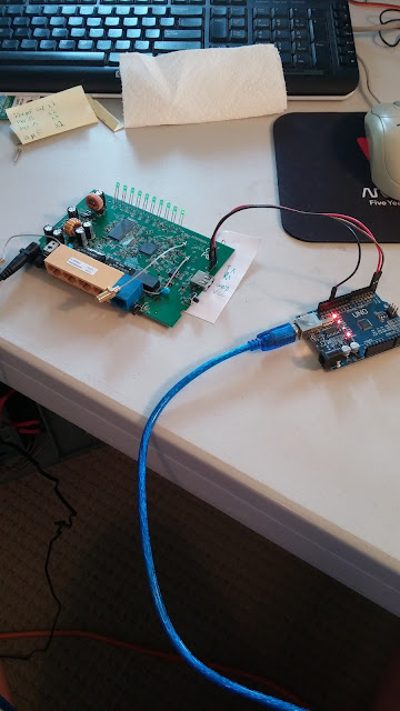
Use Arduino Uno as a USB-to-Serial Adapter

( https://oscarliang.com/use-arduino-as-usb-serial-adapter-converter/ )

I needed a USB to Serial adapter when I was trying to debug why I couldn't flash an open source firmware to a router (ended up not being able to do that).  In this website, the blogger gives three methods.  I found the sketch upload (#3) one the easiest and it worked.  I was able to then read the uboot sequence from a router I was trying to upload an open source firmware to (Couldn't do it from webflash or TFTP, couldn't find out why).


Connected to a TP-Link router

Boot sequence from serial port, not sure what's happening at very start

AM Radio as a "Bug" Detector

This is a simple but fun one.  I'm using a La Crosse weather radio. Set to AM, go to quiet frequency, then you have to get the radio within at least 3 or less inches to any kind of electrical device and you hear a very loud and ugly static noise, occasionally what sounds like some kind of clear modulating tones on some devices. One of my LCD's had a weird signature that you'd be able to pick out among my others. I tested turning off my iPad and seeing if it was still on (I think it still is but you can't really tell), and I tried it on my phone charger. When you unplug the charger, for 5 seconds or so I guess a cap is still discharging and the noise continues then promptly shuts off.

The primary use case I see for something like this would be to check that your laptop/cellphone is really off and not transmitting after turning off/removing battery (so security use cases). Of course you could get unlucky if a malware has some pre-programmed random times to transmit and you miss it. Just put your device in a static bag and metal box (padded w/ foam for audio muffling) if that's a problem for you.

Got some pics of the radio internals, this is a very hacker friendly device (but quality could be a bit better).  I did spot a 1N4148 diode up around the light, as well as some transistors, and a 100K resistor (10K's are other places), that's the AM detector circuit I suspect.

What the front looks like


When you first open case


Flipping over the PCB

Thursday, June 23, 2016

Make a Portable Packet-Sniffing Linux Box for the Raspberry Pi with tcpdump


I got one of these small TFT screens for christmas one year, finally putting it to use :)

First things first, put the screen on before powerup, don't try it while Pi is powered on.

I initially wanted Kali linux, as the UI looked better for it, but was unable to get it to work on an older RasPi.  So if you just want to download an image, here's a download link here:  https://learn.adafruit.com/adafruit-pitft-28-inch-resistive-touchscreen-display-raspberry-pi/easy-install

I HIGHLY recommend you start with the Jessie Lite version, there's still screen sizing issues even on the "pre-configured" "Full" image.  The screen sizes are off and it's really annoying to resize them anytime you open up any window.  I don't think I'm ever going to use the "startx" GUI that much for this device, too frustrating.  With the Lite version, it's not installed so you have more space on your SD card to install other programs or store data.

So get a 8GB SD card, clear out a single partition for it, and for some reason I was having issues with the Unix "dd" program on another Linux box, so Win32Disk Imager worked like a charm.  Boot up your Pi (takes a few seconds), hopefully you start seeing text scrolling.  Default username is "pi" and default password is "raspberry".  I'd atleast change the password with the "passwd" command.  Now in the initial console, I like it b/c the text doesn't go off the screen, just gets wrapped to next line.  Messing with screen resizing and the like doesn't sound like a lot of fun to me, so glad it's been taken care of within this image.

So there's a multitude of projects you can do, just search them out.  First thing is I want to change the keyboard from UK format to US format.  The quotation marks and the @ symbol are swapped.  This is done typing into shell prompt:

sudo vi /etc/default/keyboard

Push "i" to "insert" text.

Change XKBLAYOUT="uk" to XKBLAYOUT="us"

Then save by hitting ESC, you should see a colon at the bottom, then type "wq"

Then reboot by typing "sudo reboot" in the shell prompt.

Next thing is I want to use that dongle I've talked about earlier so it's not going to waste ( http://integratedmosfet.blogspot.com/2014/12/making-d-link-fr300-wifi-usb-dongle.html ), I want to automatically execute a script to add itself to a file so it'll power on.

One way to do this is found here:  http://raspberrypi.stackexchange.com/questions/8734/execute-script-on-start-up

Do the following: 

sudo nano /etc/init.d/scriptname

Write your script (don't forget #!/bin/sh).  Mine was this: 

#!/bin/sh

sudo modprobe r8712u
echo -n "07d1 3304 > /sys/bus/usb/drivers/r8712u/new_id

Then save it (ctrl-X, "Y", then enter to return to shell prompt)

Next make the script executable:

sudo chmod 755 /etc/init.d/superscript

Then register script to be run at startup:

sudo update-rc.d superscript defaults

Then reboot.  This worked for me (executes before logging in even), and I know my script executed b/c my dongle started blinking.  Now I don't have to type that script on *every* boot!  Very handy.

My Pi kept going to sleep on me, this was annoying, let's stop that.  If you always want your Pi to stay on, type:

nano ~/.bashrc

Then at the end of the file, add:

setterm -blank 0 -powerdown 0

Then ctrl + x to exit, and 'y' to save, then enter.

Next, let's set up internet, this is the easiest here:  https://learn.adafruit.com/adafruits-raspberry-pi-lesson-3-network-setup/setting-up-wifi-with-occidentalis

Just need to modify the interfaces file a bit, mostly putting in your SSID and router password.

sudo nano /etc/network/interfaces

This is what you'll need to get it working, if you for some reason have a hidden SSID, check out that linked page.  Just make sure this is what's in that file:

auto lo

iface lo inet loopback
iface eth0 inet dhcp

allow-hotplug wlan0
auto wlan0

iface wlan0 inet dhcp
    wpa-ssid "your SSID here"
    wpa-psk "your password here"

And that's it!  Save it and reboot again.

Next one cool program to try out is "wavemon".  This allows you to scan for any wifi networks in your area.  Just type "sudo apt-get install -y wavemon"

Then you need to do "sudo wavemon" to launch it.  First page is some info on your network.  Press F3 on keyboard to see the networks.  And F10 to exit.  Pretty neat, but you can't leave this running constantly which is what I want, for some reason my Pi was freezing up (I suspect a memory leak but didn't investigate).

Now for the program that this tutorial is based on, tcpdump.  This is a great program (man-page here: http://www.tcpdump.org/tcpdump_man.html ), a command-line packet sniffer.  All I personally wanted was to continuously display the packets being traversing on my network, since this is a small separate device I'll have on my desk just running all the time.  To really analyze your traffic you'd need to save all the packets for a given period of time, and analyze them later.

So, this was a piece of cake too.  Install tcpdump:

sudo apt-get install tcpdump

Once installed, just run:

sudo tcpdump

And it starts sniffing.  So far I've let this run continuously for months and it hasn't locked up the Pi.  Already I've seen my mobile phone traffic, our Apple devices, and our Xbox.  I can observe devices connecting in real-time to our network, which is nice.

*UPDATE*

First I added a wireless USB keyboard.  Most any of these keyboards, if they're standard USB keyboards should work with the raspberry pi.  I'm very pleased with it.  Since I'm using Jessie Lite, I only have command line (which is OK since a GUI on a 2.8 inch screen is not that great, and there's constant resizing issues) so the only I/O I really need is internet and a keyboard.  This makes for a very nice fun toy.

After running for around a week, and stopping, turns out around 3400 packets were dropped by the kernel and 1200 by the "interface".  I don't want any packets dropped (this is wireless so this is always possible, so I would at least be hardwired into the router if I was more serious, and probably also potentially using a device like a "LAN-tap" and store everything on terabyte hard-disks.

One concerned mentioned on the tcpdump FAQ page was connections seemingly leaking memory as address space size was increasing over time.  The developers call it "state accumulation" rather than a memory leak.  So we add "-S" to the tcpdump command.

http://www.tcpdump.org/faq.html

Also, others had this issue and suggested expanding the default buffer size to 4MB instead of 2MB. 

http://unix.stackexchange.com/questions/144794/why-would-the-kernel-drop-packets

http://serverfault.com/questions/421789/lots-of-dropped-packages-when-tcpdumping-on-busy-interface

So the latest command I'm running is:

sudo tcpdump -B 4096 -S

Wednesday, February 3, 2016

nRF_Detekt

I've been working on what I call a "homebrewed security add-on".  What I envisioned is a RF module that took a signal from an externally powered sensor and then sent on that info to another storage point.  This could be an open-source programmable security product compared to most proprietary products that you can't reprogram at least.

Version 1.1 is available on my Github account, which explains most of what I'm doing.  I'm going to add better information and more full documentation on the project most likely during the summer as I'm too busy for the time-being.  Documentation is scattered between 3 places:  here, my github, and my hackaday.io account.

https://hackaday.io/project/11751-nrfdetekt

https://github.com/Int-Mosfet/nRF_Detekt

The "architecture" of the project has changed quite a bit, especially when I could encrypt more than 8 bytes lol. I can encrypt basically any block size that can fit in the ATMEGA328p with this encryption algorithm, CPU-wise and with flash ROM and RAM.

Right now I have XTEA and then AES-128-ECB (I know ECB ECB ECB!! It'll get complicated real quick (AKA subject to crazy failures that get too hard to debug) if I send out the IV generated on the TX node to RX node (after at least encrypting with XTEA with a separate key) then encrypt with the more secure mode of AES-CBC. Still, who can crack AES-ECB after chaining with other ciphers? No one as of now. Don't fall for the FUD, I'm taking care of using ECB mode, not like an idiot encrypting same string like IP address or something like that.) encryption of a 32-byte struct working well. I can chain on more ciphers but I think max I'm going to do now is Keeloq (which I am doing now), and just repeat the chain. I want this to be easy, adding in some of these other ciphers so they're ready for showtime, it's going to take a bit of work crafting them. Advanced users could do that easy, non-advanced users that want to just flash what I have, don't worry this default can repel basically all cryptanalysis as of right now. To break the crypto, you need an end-run attack as of now. Meaning stealing the key as you flash it in, or it leaks somehow during operation.

I worked pretty hard, thinking thinking thinking how to do a channel-changing feature that was robust and above all SIMPLE (simple was my overriding design goal). I can do it, it works in my room, but it's not *ULTRA* reliable which is what I want. So, if power fails (or that node gets jammed/attacked) on RX in the microseconds that the receiver has acknowledged back to TX that it has received, BEFORE I INCREMENT THE CHANNEL NUMBER, then the units will be out of sync with my simple algorithm. What I want is, to "randomly" change channels to throw off an eavesdropper, make it pretty annoying trying to lock on. If a fail mode happens in the TX, then to keep transmitting on every channel until it finds RX. RX would then have to stay on a channel so TX could find it or they may keep searching for each other indefinitely... So this channel changing feature gets murky real quick. For now I'm settling on statically setting one, by choosing some of my researched channels (you have to research channels that work in your area yourself) and other countermeasures will be needed to deal w/ active eavesdroppers. Which is expected with this project anyway. Much more is needed to repel and defeat these attackers.

I store this channel, and an "activation number" in the EEPROM. So it remains thru powercycles. I'm displaying this on a LCD attached to the receiver, which will be on my desk as a cool little device telling me if something is entering somewhere. The amount of writes I can do to EEPROM worry me (~100,000), so I may add in a little feature where I increment where I'm writing, then store address too (since on a powercycle it would just go to first set address). Or I may just say use that address up, then move on. Or to swap out chips if the EEPROM starts failing. This should, if you have 100 activations a day, take you around a 1000 days to happen, or 2.7 years. I set the speed of the radio comms to minimum (250kbps), CRC to max (16 bits), power to max; all my settings are to maximize RELIABILITY now instead of STEALTH.

***POWER*** Power to the nRF24 was not sufficient. I can solve this multiple ways. I did manage to get my hands on a LM317T voltage regulator. If you google "lm317 3.3 volt power supply" you'll get a schematic for a very nice and easy to build step-down regulator. Here's all you need: http://3.bp.blogspot.com/-N8fWdFhlouc/TnRG85acliI/AAAAAAAAA5k/dPA56ZxMfQ0/s1600/3.3V+regulated.jpg Get those parts, and you can use the 5V output pin of the Arduino, and this will step that down for you and provide plenty of current for the nRF24 with a PA and LNA (we need around 130mA, while the 3.3V pin of the Arduino can provide max of 50mA). That was too many components though, I don't want that (even though it's nice and works). Next thing you could do is use a transistor as an amplifier, and that will work. An NPN transistor (2N3904) would work with a resistor connected to the base I belive. But I was a little nervous since I'm not a EE, I can hook it up (I've use an NPN transistor as a switch for my radio, and it worked like a charm), but don't want to take any chances with my Arduino boards. What I think will work best for me (since I want minimal soldering and parts on the proto board, since I'm going to be putting this in a box), is a AMS1117 5V-3.3V buck converter. I believe it will work well. I'm going to be ordering one very shortly. I can power it via the 5V output pin, which will supply plenty current (400-500mA on USB and 800-1000mA on DC power), then it will be able to supply the nRF24 radio w/ upto 800mA current (which is way beyond what it needs). I will probably have to add some shielding to the radio, and maybe another filter on the input (a low pass filter, just a capacitor from VCC to GND).

So...those are the main changes right now to the project. After this code update and I get the power supply providing enough power to the radio for max power, I'm going to move on to other projects. BUT, I will keep revisiting this project, because like I said, I know it can be much better and it will get better. I'm going to be working on it for some years until I get it where I can finally say "I'm done". 

Some pictures, the final product will look a little different.  I'll be working on mostly software off and on until summer, when I want to crank out final versions of it.


Soldering nRF24L01+ to Arduino proto-board

Finished Prototypes

How I connect to units, I'm blanking out the sensor for NDA reasons, recommend 2 PC's if developing.

Thursday, January 21, 2016

Avalanche-Noise Based (Pseudo) Random Value Generator

Randomness is a hard problem.  There is no definition to it.  However, there is a lot of research into just what exactly is...randomness.  As anyone who studies cryptography will tell you, having randomness while generating keys is one of the most important parts of protecting information.  I was interested in this so I looked into some solutions.  One of which is this circuit, there are other more simple versions, the noise is generally from a zener diode.

I have since moved onto other projects, so this post won't detail my build as much back when I did this last summer (I need to keep up with my blogging, it's just more work. :p ).  The source for this project is this site:  holdenc.altervista.org/avalanche/  The best resource is this site though: https://www.cs.helsinki.fi/u/oottela/tfc-manual.pdf . Make sure you get all the parts, and lay it out on a breadboard to test.  It's easiest if you have access to a newer digital oscilloscope too.  Look up the pinout of a transistor, pinout of the TL082 op-amp, and make sure your 1N4148 diodes have the correct polarity.  I got lucky and the circuit worked on the first power-up (after tuning with an oscilloscope of course).

Oh, the most useful part of this project was how simple it was to capture the entropy of the voltage levels (this is what is random...), was to use the "analogRead()" function in the Arduino toolchain.  It would be handy to take that info and store in a SD card, but that's a project for some time else.

Using analogRead() Arduino example code works ( https://www.arduino.cc/en/Reference/AnalogRead ), and it's very easy to modify it to your needs.  Pictured is my breadboard implementation, take your time and build the circuit, it's a nice feeling when it's done and you start sampling.  I may try to make a PC board of this circuit, which would be nice, will post here of course if I do.

Here's the circuit, enjoy the build if you decide to do it: