http://www.instructables.com/id/PC-Mouse-Robot/
That didn't pan out well because of size constraints and I didn't want to spend a lot of time on this project. So I went and got a little AA battery pack as the motor that I'm using is a 3V one from a broken shaver (the motor still worked for some reason).
I also had this I believe is capacitive touch module that was given to me, and it lights up. Hope the battery in it lasts for a little while longer as it's sealed in there pretty good.
I decided to just do a simple switch on and off, which will spin the mouse's face. Pretty silly, eh? Well, hopefully it'll make someone smile...
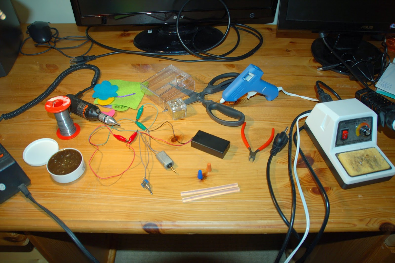
Materials needed are quite a bit for what is mostly an "arts & crafts" project:
--Glue gun
--Plastic box
--3V DC motor
--AA battery pack for 2 AA's
--Soldering iron / solder
--Felt materials, anything decorative
--Wire cutters
--Dremel tool
--Foam with sticky side
--A switch
--2 twist-on wire connectors
--Scissors
1) Plan your layout, and dremel holes into the plastic box. Make note of dimensions and how things will fit was all packed in. I didn't get really specific here, just a lot of "eyeball" measurements.
2) Connecting the motor, switch, and 3V from the batteries is fairly straight forward. There's 3 leads off the switch, the power source goes on the 2 exterior leads. If you only have one power source, you can leave the other outside lead blank. And ground (technically the "relay") is the center lead. Hopefully your motor marks (+) and (-), otherwise just find that out before you begin placing it in the box. All 3 wires can be twisted together with a twist-on wire connector.
3) Add any decorations you want, mine's pretty silly and pretty bad. I'm no artist. :p
4) Drill out a hole for the motor and I just glued the mouse's face to the end, so it should spin in circles really fast. Drill out a hole for the switch, and I applied copious amounts of glue to hold it in place.
5) I left the battery case unglued in the event batteries need replacing. It's held mostly in place by the motor and some more foam pads.
/***** WARNING *****/
This design has issues that have yet to be resolved. Testing showed that the circuit was OK, but final product showed it clearly wasn't. Batteries get discharged extremely fast and get really hot (can burn you). This means that there is resistance somewhere in the circuit allowing this leakage, or a fundamental flaw in my circuit (I tried to keep it as simple as possible). I heard that it could be a bad switch, which is frustrating.
So, be sure to test your circuit extensively. And a good-looking and functioning "robot" won't turn out on the first run usually.


2 comments:
It made me smile with pain in my middle finger~ahhhh~~ haha that was a cute robot!
Oh, so sorry about that! :/ I said don't touch! haha It's the thought that counts right?
Post a Comment