Monday, September 8, 2014

Removing Laptop WIFI Card and Camera/Microphone

So I've had some problems in the past with my Wifi/Bluetooth card and in turn the camera/microphone.  For some reason, when I didn't want any Bluetooth communications, it would turn on.  Trying to turn it off would be beyond my control.  I can end that problem by reinstalling Windows (which removes drivers) and not re-install Bluetooth drivers, and that seemed to work pretty well.  Sometimes though, I like to have an "air-gapped" computer, which means that the computer doesn't have any means of connecting to standardized communication protocols (TCP/IP, 802.11, Bluetooth LE, etc.).  For instance, if you are generating cryptographic keys on your computer for let's say PGP emails, you want to be sure that you aren't leaking those keys to a network somewhere.  There are of course still ways to capture data, but these require specialized knowledge and tools and this is a whole other topic of TEMPEST/EMSEC in computing which I won't get into today.  Removing the Wifi card is a big step.

Also I'm not much of a Skype user or a big "selfie" kind of guy and don't really have a need for a camera/microphone on my laptop.  It's just a security risk and unnecessary bloat on my computer as far as I'm concerned and there have been instances of voyeurs using malware to capture intimate moments when someone left their laptop open in their bedroom...

So if you're like me and don't need to have all this connectivity on every device you own, we want to modify that.  The laptop being used in the tutorial is a Fujitsu Lifebook A-Series.


List of Materials:
--Laptop
--Knife or paint scraper
--Screw driver
--Wire cutters

Most of the tutorial is using your hands to pry open lots of areas, very manual-intensive project.

To start, here's my working computer with the Wifi card:


1) Now flip over, take out the battery and begin taking out a lot of screws.  I won't even circle them all in pictures, there's something like 23 screws just for the exterior to be able to pry apart the plastic cover.  So just be cautious and keep track of every screw you take out.  Take out the hard drive too, it's about a 3X4" rectangle near bottom left in the picture; should slide out pretty easy.

2) Now once you're certain all screws have been removed, you can pry open a fairly large plastic cover on the bottom.  It takes a little bit of "elbow grease" to get off, and I was intially worried about breaking it.  But it will snap out.  JUST MAKE SURE YOU HAVE ALL SCREWS OUT or you may break some plastic.  Luckily for Fujitsu laptop owners, the Wifi card is right there (my finger is pointing to it).  It's held in by 1 screw and the antennas just popoff and you can pull it out.


3) However the antenna disappears to the other side and I don't want to leave that in.  Can't be yanked out.  Also at this point take out the CDROM too before you go to the other side.  There is one screw holding it in and you can use a paper clip or thin-metal object to insert in a hole by the outside to open it and just pull the unit out.


4) Now flip over to the front of the laptop.  You can pry open the speaker cover with your prying-tool of choice (needs to be thin enough) and pop that cover off.  You will see the underside of the power button and a couple speakers, as well as the hinges for the LCD screen and the screws needed to remove it.  Also you can pop out the keyboard BUT BE VERY CAREFUL as I popped out the thin cable for the keyboard and nearly needed to go to a repair shop.  You really don't need to take out the keyboard for this though, but you might as well take a peek now anyway if you want.  The Wifi antenna continues on up the right hinge up into the LCD screen, so we need to remove that.


5) Now there's 2 screws holding the screen to the computer, take them off and lift up the LCD screen.  You can pull the antenna thru so the screen can be completely removed.  Again, be cautious and patient so you don't end up need a new LCD screen.


6) There's 4 screws on the outside corners of the screen, which are covered up with black rubber bumpers.  You have to pop those off and unscrew the screws.  Prying it open carefully, you can see the antenna going up the right side.  Keep pulling it out and moving up to the embedded camera/microphone at the top of the screen.  There you'll see the antennas soldered to be held in place and the 2 antennas aren't the same size.  Snip them off with wire cutters and you got all the antennas.  Down the backside of the LCD is where the camera/microphone get power.  I simply snipped that with wire cutters and pulled out the camera/microphone.


7) Here's the removed components, antennas, Wifi card, and camera/microphone.  It's an Intel Centrino Wireless-N-1030 module with Bluetooth.  I don't know what brand the camera/microphone is.

[PDF WARNING]

http://www.intel.com/content/dam/www/public/us/en/documents/product-briefs/centrino-wireless-n-1030-brief.pdf


8) And now you have to reverse everything you did and put everything back together.  You should do it as soon as possible and not put it off because you may forget some things.  Here's my laptop working again, and hmm..It was having trouble finding the Intel Wireless card, huh..weird. :P  Connecting to wifi is still possible with the multitude of wifi-USB modules that are available, I have an old D-Link one and I just needed to download a driver from a website (on another computer of course!).  And now I can connect to wifi when I want and have a reasonable assurance that when I don't want to, it's close to not possible.  Speakers stayed in but I may remove them too in the future.  Be safe and protect yourself.


Monday, August 18, 2014

Installing Puppy Linux to Hard Drive

I was having some trouble that I felt was unnecessary, trying to install Puppy Linux to a hard drive (HDD) on an older computer.  The Puppy Universal Installer makes it easy, but I was messing something up.

This post assumes you just want Puppy Linux on your HDD, so no partitioning to make it simpler (I would recommend this to only PC's you keep off the internet).  Otherwise, you would have to use a program like GParted and partition your drive how you want (maybe even encrypt for extra security).

Before you begin, first you should already have a copy of bootable Puppy Linux on a USB stick or CD/DVD, previous posts show how to do that and the procedure stays the same mostly and is pretty easy.

You need to check the type of your HDD as Puppy Linux will ask you in the Universal Installer.  Check to do the Full Install and not Frugal (unless you want to use the HDD for something else, putting Puppy Linux on a HDD is assuming the computer is old and can't run much else with modern speed and convience).

These parts were all pretty self-explanatory.  What's tricky is after you get done.  DO NOT DELETE THE TEXT FILE THAT COMES UP AFTER INSTALL.  You need it.  Set up Grub4Dos and install on the MBR.  Mostly point and click setup that's made easy for you.  Now, *IF* you have a IDE-base HDD, you should change the line in the menu.lst file.  Otherwise the install won't work.  It's about 3 lines.  Copy the lines from the text file and paste into menu.lst.

This should work and you should be able to boot Puppy Linux from your HDD now.

Questions in the comments if you have any.


Simplified USB Wiping Via Linux Command-Line

Method taken from: [ http://www.pendrivelinux.com/restoring-your-usb-key-partition/ ]

They have a universal live USB-stick program that works in windows very easy and consistent (which means there's code bloat that you don't need, but it's OK to get to simpler OS's)

1. Note any drives you have plugged in.
2. Plug in stick and note drive letter (sdx) x being some letter.
3. Open terminal and type "fdisk -l", that's a lowercase "L".
4. Type "fdisk /dev/sdx" (replace x w/ drive letter, don't add the number if there is one)
5. Type "d" to delete partition.
6. Type "1" to select 1st partition (and go thru typing "d" and deleting all partitions)
7. Type "n" to make new partition.
8. Type "p" to make partition primary.
9. Type "1" to make it first partition.
10. Press "enter" to accept default first cylinder. If there's a virus in those 2000+ blocks, you can't solve that yet if you're doing this. Start somewhere, practice, research, learn, and kill the malware eventually; but not yet. Press "enter" again to accept default last cylinder.
11. Type "w" to write new partition to USB-stick.
12. Type "umount /dev/sdx1" (again replace 'x' w/ drive letter).
13. Type "mkfs.vfat -F 32 /dev/sdx1" (again replace the 'x'). Had a little hiccup on my end when messing around, doing "mkfs.vfat -t /dev/sdx1" got me back to reading the USB stick again for unknown reasons.

You can load the drive w/ whatever massive file[s] and then delete again if it makes you feel better. If you're up to it, try to learn the actual (likely C) code and corresponding Assembly code (you can keep going deeper if you want) and find compilers/assemblers you trust or make one yourself if you're truly badass.


/***** NOTE *****/

It may help to use the "Format" utility in the OS first too.  But this procedure works pretty good, just not 100% as there's still all sorts of weird things that can happen and this uses less code than downloading another program to do everything for you automatically (and not doing a full wipe perhaps).

Making a Simple "Robot" From 3V DC Motor and Switch

This tutorial came about as I made a promise to a friend to make her a "robot".  My initial plan was to gut a computer mouse and make one of those robots you see here:

http://www.instructables.com/id/PC-Mouse-Robot/

That didn't pan out well because of size constraints and I didn't want to spend a lot of time on this project.  So I went and got a little AA battery pack as the motor that I'm using is a 3V one from a broken shaver (the motor still worked for some reason).

I also had this I believe is capacitive touch module that was given to me, and it lights up.  Hope the battery in it lasts for a little while longer as it's sealed in there pretty good.

I decided to just do a simple switch on and off, which will spin the mouse's face.  Pretty silly, eh?  Well, hopefully it'll make someone smile...

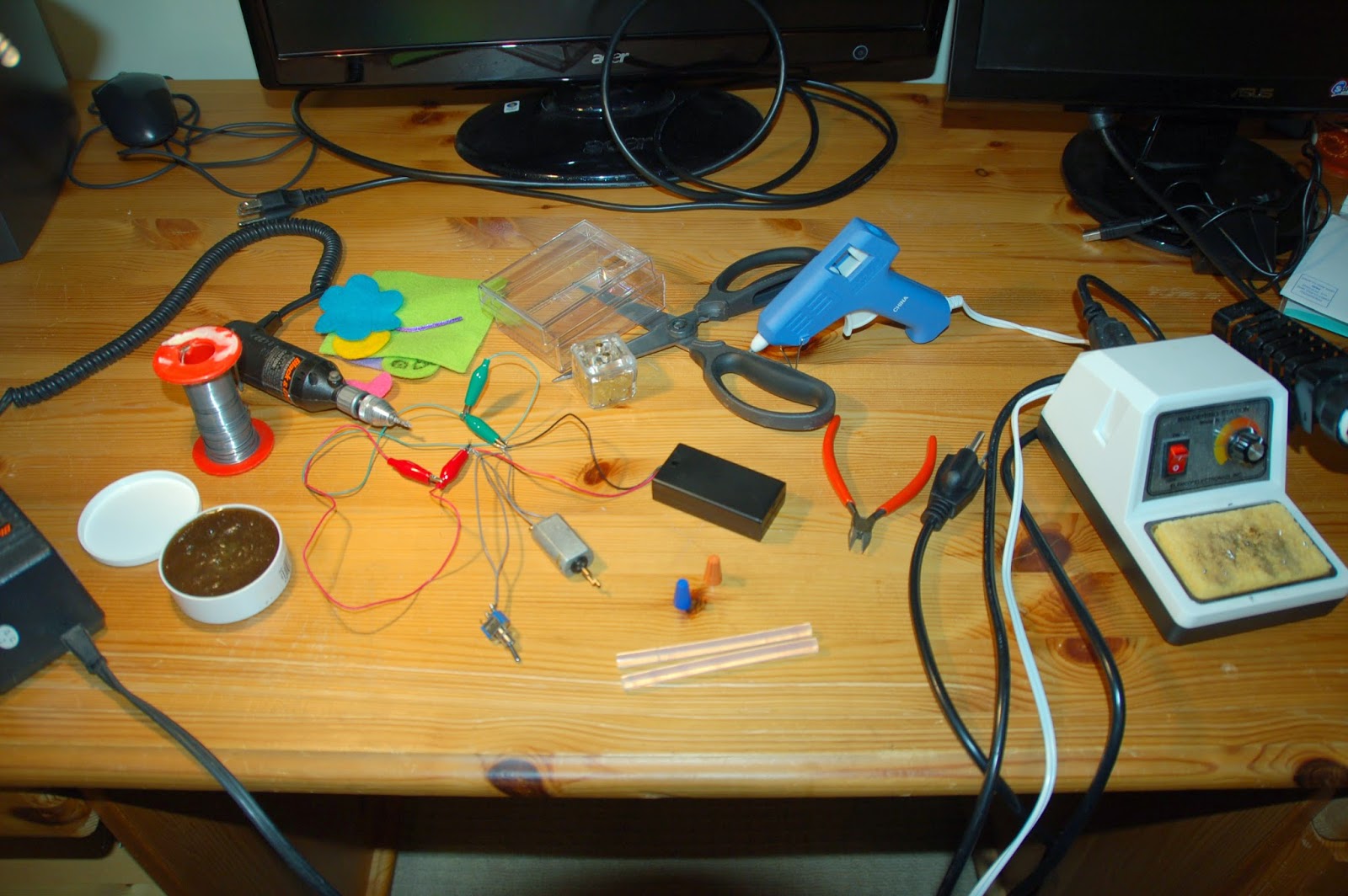
Materials needed are quite a bit for what is mostly an "arts & crafts" project:
--Glue gun
--Plastic box
--3V DC motor
--AA battery pack for 2 AA's
--Soldering iron / solder
--Felt materials, anything decorative
--Wire cutters
--Dremel tool
--Foam with sticky side
--A switch
--2 twist-on wire connectors
--Scissors

1) Plan your layout, and dremel holes into the plastic box.  Make note of dimensions and how things will fit was all packed in.  I didn't get really specific here, just a lot of "eyeball" measurements.

2) Connecting the motor, switch, and 3V from the batteries is fairly straight forward.  There's 3 leads off the switch, the power source goes on the 2 exterior leads.  If you only have one power source, you can leave the other outside lead blank.  And ground (technically the "relay") is the center lead.  Hopefully your motor marks (+) and (-), otherwise just find that out before you begin placing it in the box.  All 3 wires can be twisted together with a twist-on wire connector.

3) Add any decorations you want, mine's pretty silly and pretty bad.  I'm no artist. :p

4) Drill out a hole for the motor and I just glued the mouse's face to the end, so it should spin in circles really fast.  Drill out a hole for the switch, and I applied copious amounts of glue to hold it in place.

5) I left the battery case unglued in the event batteries need replacing.  It's held mostly in place by the motor and some more foam pads.

/***** WARNING *****/

This design has issues that have yet to be resolved.  Testing showed that the circuit was OK, but final product showed it clearly wasn't.  Batteries get discharged extremely fast and get really hot (can burn you).  This means that there is resistance somewhere in the circuit allowing this leakage, or a fundamental flaw in my circuit (I tried to keep it as simple as possible).  I heard that it could be a bad switch, which is frustrating.

So, be sure to test your circuit extensively.  And a good-looking and functioning "robot" won't turn out on the first run usually.


Reflashing a Linksys E2500 Router with DD-WRT Firmware

Have an extra router laying around (I plan on doing a cooler radio tutorial with the classic Linksys WRT54G router later) and I felt like reflashing the firmware; meh, why not?

This isn't necessarily something that needs a tutorial as the DD-WRT wiki pages and their walkthroughs are pretty thorough (yet still a little bit scattered on some parts, but pretty good), but having now done it, I think I could condense some of the reading (it's not very much) and make it even easier and faster to reflash firmware with confidence.

/***** WARNING *****/

This is a potentially very dangerous operation (danger is my middle name :P ) because if you don't strictly follow the procedures you could either write the wrong file size or begin writing to the NVRAM in the wrong place, thus "bricking" your router. Which usually means you now have a new plastic box and a scrap-board to get some spare parts off of...  While it's not 100% gone if you do this (there's some recovery procedures given, you would have to make or buy a JTAG connector), you really don't want to be messing around with all the frustrating errors and potentially permanent damage to flash chips, unless you enjoy learning and hacking it (I kind of do), then by all means brick your router and try to fix it!  Speaking of which, that would be a good tutorial to do...

So for the list of materials, you need:
--Linksys E2500 router
--12V power supply for the router
--A standard Ethernet cable
--Stopwatch
--A computer with an Ethernet port and web browser
--Software (firmware .bin files from online)
--Saved HTML webpages for offline use
--Thin button pusher for the router reset button (could be many things, so get creative)

1) First, check to see if your router has been ported with DD-WRT.  Initially I was going to flash Open-WRT but they didn't support the E2500, I was glad to see DD-WRT did though.  Odds are, you can flash some open firmware on your router.

2) Start off firstly by reading up on how to do this.  Once you do it, it's really not that bad; actually quite easy.  The firmware writing and porting is the real hard work.  Keep reading until you feel comfortable.  All it took for me was these pages:

http://dd-wrt.com/wiki/index.php/Linksys_E2500
http://www.dd-wrt.com/wiki/index.php/Installation
http://www.dd-wrt.com/phpBB2/viewtopic.php?t=51486

Download and save all these pages and of course the binary firmware files to a thumb-drive or your hard-drive for off-line viewing, you can keep a separate device to still look things up online too.

3) Now the most annoying part of flashing router firmware, in my opinion, is the "30/30/30" reset.  I've never heard of it nor seen it in my limited embedded development experience.  You have the router plugged in, and while plugged in, you need to hold the reset button (not the one on front, but on bottom of the device) for 30 seconds, then still holding the reset button, unplug the router for 30 seconds, then still holding the reset button, plug the router back in for 30 more seconds; totally 90 seconds of holding the reset button.

Make sure you have a little thin solid object to hold down the reset button and that you situate the router and your hands such that you can easily unplug and plug in the router while holding the button down.  This is the hardest part of flashing, in my opinion, so not that hard.

4) Next connect your ethernet cable to the computer and your router.  Since you shouldn't be connected to the internet, disable as many plug-ins and add-ons, virus protection, and clear caches; just to avoid some funny errors.  Log into the web interface (type 192.168.1.1 into your browser).  Now, they recommend to strictly use Internet Explorer (the default Microsoft browser) but I was able to flash the router just fine with the open-source Iceweasel browser, which is very much like Firefox.  If you already have IE and you're on Windows, then go ahead and use that first.  It's funny because at where I'm interning now, Internet Explorer by default worked the best with a product, instead of say Google Chrome.

Anyway, the default User name for the E2500 (with Cisco firmware) is "root" and the default password is "admin".  Now click on "Administration" tab, then "Firmware Upgrade".  You should already have the firmware file.

/***** WARNING *****/

Make sure the firmware file is the "mini" one, read the file name used in the picture.  DO NOT FLASH ANY OTHER FILE BESIDES THIS ONE FIRST.  Another part here where you could really brick the router.  This file is needed before you can flash some other custom DD-WRT firmware.

5) So browse and find the file where you downloaded it, and click "Start Upgrade".  Now, here's why I said you need a stopwatch.  Wait for 5 minutes after you flash, to "insure integrity" as they say.  Then after that, unplug the router for 10 seconds to power cycle and wait for 3 minutes after plugging back in.  Then do yet another 30/30/30 reset.  Then wait for 3 minutes to plug in the ethernet cable and log into the web interface.

And that's it! Congrats you flashed the firmware!  Now you can download and flash other custom DD-WRT firmware.  Just make sure it's no bigger than 8MB and is specifically for the E2500!  Follow the same procedure above to reflash.  I honestly didn't see that many more new features in the "big" firmware than in the "mini", so I may try another one.

Depending on your knowledge of the internet and networking, you can customize a lot of settings in the router.  Like port settings, MAC-addresses allowed on, IP-logs, VPN settings, and on and on...I would leave most of the settings as default if you don't know them, and add the highest encryption (WPA2/AES) with a large key (63 chars), like you would make a secure password that's hard to crack.  You could also disable WDS as there's a tool to hack into routers using this PIN number...

Also, if this is another router not connected to your modem, you can go to Setup -> Advanced Routing -> Operating Mode, and select "Router" to establish a link.  There's another page for doing that as well:

http://www.dd-wrt.com/wiki/index.php/Wlan_Repeater

This covers it pretty well but I wasn't able to get it to work exactly how I wanted.  You have to disable a lot of security to do it, and I don't feel comfortable doing that.  I also don't have my own internet connection.  I'll eventually get it working how I want, and will update this post when I do.


Thursday, May 8, 2014

Troubleshooting a Casio Cassiopeia E-115

It's been a while since I've posted, glad to be back hopefully helping someone out there.  Recently I went through the unfinished storage in my house and dug out all the old technology we had.  I found all sorts of nostalgia-inducing toys and knickknacks.  An old CD-ROM harvested from an old computer still worked like a charm, it's a lot of fun bring old electronics back to life.

The focus of this post however is a Casio Cassiopeia E-115, I remember when it came out and it "was all the rage".  I think devices like this foreshadowed the enormous smartphone market of today; cell phones were still rather basic machines then and remained so for a while.  Anyway I found this and was unable to power it up (it's been sitting dormant for over 10 years) even with AC power.  This was really personally frustrating and researching it online didn't fill me with a lot of hope.  Alas, when it finally booted up for me I was overjoyed, and it turned out to be a hilariously simple solution (but I still have some further investigating to do).

Materials need for this tutorial:


--Multimeter
--Electrical tape
--Spare wire
--Wire cutters
--Small screw drivers
--Digital power supply
--Cassiopeia E-115 with battery and AC power unit

1)  You have a Cassiopeia E-115 (or any of the E-100's series and possibly others), but it will not turn on (which is a common problem that develops).  First problem to look into is power.  Get out a multimeter.  Now switch it to 20 V DC (straight line with dots), it's all you need here.  First, check inside the main battery area, with the battery charging.  When flipped over, the right side is negative, the middle is "T" for thermistor, and the left is the positive contact.  If you're wondering what the thermistor is, check out the links I list below.  Battery packs are becoming smarter and modern battery packs will even have a microprocessor (!) checking temperature and battery life constantly.

Put the postive (red) probe on the positive contact, and the negative (black) probe on the negative contact (it's best while battery is in and plugged in).  Now, according to research, which I link to at the bottom, the correct voltage should be anywhere from 3.5 V - 4.0 V.  If this is what you read then you may have a blown fuse; but the device should be able to turn on still with AC power if this is the case.
If the voltage is below 2.5 V (mine was 0.18 V) then you likely have a bad battery or charging circuit.  Hopefully it's just a bad battery as a charging circuit takes a lot more work to remedy.  If the battery is bad it will pull the AC adapter voltage down to a level where it can't start the device.  Step 2 will describe a neat trick to try next.

2)  Cover the "+" contact on the battery with electrical tape and put the battery in.  This is to ensure the connection of the internal thermistor across the "T" and "-" contacts.  If it now turns on, then a bad battery is a likely culprit.  If it still doesn't turn on, then a bad charging circuit may be the problem (which is the worst as I don't know currently where it is or how to replace it in a "DIY" way).  However, it may not be that so don't give up yet.  Now we will begin opening up the device (let the fun begin!).

3)  Now you need a small screw driver.  There are 2 easily accessible screws on the back and 2 inside the main battery area.  Unscrew them and carefully peel apart the device, the middle part is a little tough so just take your time. 

And be sure not to pull apart very far as the back up battery is connected to the outer cover.  It's not the end of the world, but just something you'd have to solder back.

Pretty board, isn't it?  Now next thing to check , which I find silly, is the microswitch between the main and back-up battery.  Apparently some people were able to get the device to turn on after flipping the switch a few times.  I'm not 100% what they were talking about but there's a small white switch right above the main battery pack area and you can also move the actually switch on the outside back cover too.  This didn't do anything for me.  Also there a rather large capacitor near where you plug in AC power on bottom right, use you mulitimeter to see it you get any voltage (I got 5.2 V, which meant there's power coming in, and there's a problem on the board somewhere).  If that silly trick didn't work, go to step 4.

4)  Now we're going to go deeper.  Someone online was able to get his Cassiopeia to boot up by cleaning the ROM-board contacts.  The ROM board is a small ~1.2 X 1.2 inch board screwed in to the back PCB.  Now, be careful (!) as the manufacturers put some light glue on the screws.  It's very easy to wear away the threads of the screw.  I actually did that for one screw, and was able to use a dremel tool to grind away the screw and pull the board up; but I would try to avoid that.  Scrap away some of the glue around the edges of the screw, being careful not to hit any of the PCB leads.  Now pull off the chip; it's the ROM board!  This is the part of this computer that never changes on any boot up.  Use a tiny clothe stick and some contact cleaner to ensure good contact, put back on and try to boot up again.  If you have the same predicament as me, it still wouldn't boot up!  On to step 5.


5)  Ok, so we've exhausted a lot of options, basically all the ones I've seen online.  If your device still won't boot after this then I'm not sure right now what the problem is.  Also, a bad hardware component or entire circuit will be very difficult to pin down and fix; you may have to resort to another electronic repair place or Casio support.  Now, get ready to laugh at how easy my solution was (to at least get a power-up).  As I did in a previous tutorial, I widdled the plastic off some wires on both ends and connected them to my digital power supply and wrapped them around the positive and negative leads in the main battery area (make sure "+" to "+" and "-" to "-").  I set the digital power supply to 3.7 V (the amount on the battery) and had AC power plugged in.  And...IT FINALLY BOOTED UP!  :)


I was able to play some Solitaire and explore the device I had forgotten about.  Next up, I would really like to get Linux running on it, but there's not much out there, so that's an iffy prospect.  Now I need to investigate where the charge circuit is and get my Cassiopeia running with pure battery power.  As always, feel free to ask questions, I'll do my best to answer any.


Research Links:

--en.wikipedia.org/wiki/Thermistor
--electronics.stackexchange.com/questions/10588/why-are-there-3-pins-on-some-batteries
--www.youtube.com/watch?v=l0TT5CnbwBQ
--pdadb.net/index.php?m=specs&id=11&view=1&c=casio_cassiopeia_e-115
--www.amorphix.net/cid=256
--forums.enterprisemobiletoday.com/showthread.php?12701-E115-power-problem

Monday, February 3, 2014

Simple Amateur Radio Morse Beacon

If you aren't an Amateur Radio operator, and you're in engineering/computer science, you should check it out.  It's very simple to get a Technician license (what I currently have as of 2/3/14) as they give you all the test questions (and answers) for the test and there's no longer a Morse Code requirement (copy and send at least 5 words per minute (wpm).  This license they lets you dig in the world that is radio; if anything it will strengthen your understanding of electronics and physics.

Well as the title suggests, this little project took me about an hour (takes time to plug in cords and get pictures) to do.  A "beacon" is basically an automated message playing over and over typically on HF bands.  Nowadays, aside from QSL cards which Hams send to each other to verify a contact, there are many online and computerized logbooks.  Sometimes you can find out if an area of the world is receiving your signal based off your beacon operation.

For this tutorial, you need:
--Soldering iron and solder
--Radio (I'm using Kenwood TS-130S) and accompanying power supply
--Arduino Uno
--4 jumper wires
--1 breadboard
--2 aligator clips
--Wire cutters and some spare wire
--BC 337-16 NPN Transitor
--1/4" Audio Jack

Now to begin:

1) Using wire cutters, you gently squeeze around the wire to cut the outside plastic.  When you have weakened the outside plastic in a circle around the wire, you grasp (be careful depending on how thin the wire is, it'll probably take a few times until you get it) with the cutters and slide the plastic off, exposing the metal wires.  Do this for 2 pieces of wire on each end.  For the purposes of demo-ing this, I used aligator clips to grab the ends going to the audio jack and also the jumper wires going back to the breadboard.

2) Now take the transistor, with the flat side facing you.  The NPN transistor has a collector, base, and emitter terminal for different layers in that order.  So with the flat side facing you, C for collector, B for base, and E for emitter.  Remember that.  Place it in the breadboard, make sure the connection is snug.

3) Now whip out your soldering iron.  There isn't much to solder here so if you're not good at it, don't worry.  Now you need to take one of those cut wires from step 1 and wrap the metal around one of the the insides.  The longer one is the SLEEVE or GROUND for the EMITTER on the transistor.  The shorter one is the TIP or SIGNAL for the COLLECTOR on the transistor.  The base on the transistor goes into pin 13 (which will make more sense when I show the code).

4) Now we will flash code onto the Arduino.  Make sure you know how to do this before continuing here.  The code, I copied (maybe I'll write my own soon, it wouldn't be hard) from here, check out his site it's good.  In the "Setup" portion of the code, you can change the start-up message to whatever you want, and then the "Loop" portion is what will be constantly transmitted by your radio.  Flash this code on your Arduino.

5) Now, since the code conviently used pin 13, we don't need to add a 1K resistor (MAKE SURE TO CHECK IF YOUR ARDUINO IS NEWER SO IT HAS THIS RESISTOR, or you may damage it).  Now from here it's very simple, we just connect the COLLECTOR to SIGNAL on audio jack, BASE to pin 13, and EMITTER to GROUND in the audio jack AND GROUND on the Arduino board.  Now give power to the Arduino and plug in the audio jack to your radio, if it doesn't work let me know your set-up, I had some funny issues and maybe some contact issues with the breadboard; but it was great to hear it work!

*Note that I used a 1/4 inch audio jack that actually went into my radio, with a smaller audio jack going into it.  The audio jacks on older radios are bigger, no modern headphones would be able to plug in with out an adapter of sorts.

*I was supposed to have this up and running with an LCD screen displaying the message for my dad for Christmas, I enjoyed break a little too much and got caught up in other programming languages.  When I add that functionality I will update this blog post.  I may also add some sort of message input functionality from the LCD screen with an EEPROM chip, we'll see.